Trinamic TMCs drivers in Zephyr RTOS
Introduction to the Zephyr RTOS driver for the TMC51xx series of motor ICs from TRINAMIC.
Dependencies
A fork of the TMC-API is used, for reusability of the header files and definitions published and maintained by Trinamic (now ADI). The fork is needed since Zephyr-related PRs have been repeatedly rejected by the company (see #31, #52).
When the zephyr-trinamic module is used in an application, the TMC-API dependency is pulled-in automatically via the project manifest.
The fork simply add few CMake and config files to enable to build it in Zephyr:
State of the art
The driver supports both SPI and UART communication protocols, on top of the STEP/DIR signal to control speed and direction rotation. It provides a set of console commands to configure the driver and to run the stepper motor in velocity or position mode, using the internal ramp generator. Source code can be downloaded from GitHub.
TODOs
- implement the full Sensor API to set/get driver parameters
STEP/DIR interface
The driver relies on the MCU’s hardware timers and Zephyr’s PWM API to generate the step pulses to rotate a stepper motor.
In the devicetree (or overlay) file, at least one PWM node (child of a timer node) shall be enabled.
With reference to the STM32 PWM binding, the PWM period is defined in the pwms cell of the TMC (see snippet below).
# STEP/DIR configuration for the ST Nucleo F103

&timers1 {
    status = "okay";
    st,prescaler = <100>;

    stepper0: pwm {
        status = "okay";
        # PA8 is the step pin, which is attached to TIM1 channel 1 on the F103
        pinctrl-0 = < &tim1_ch1_pwm_pa8 >;
        pinctrl-names = "default";
    };
};

&spi2 {
    #...
    tmc_0: tmc5160@0 {
        #...
        # STEP - pwms cell linked to the pwm defined above, using channel 1 with period 10000ns and in normal polarity
        pwms = <&stepper0 1 10000 PWM_POLARITY_NORMAL>;
        # DIR - a simple gpio
        dir-gpios = <&gpioc 7 GPIO_ACTIVE_HIGH>;
        #...
    };
};
The driver change the motor speed setting the PWM period and direction:
struct tmc_config *cfg = dev->config;

// period (in ns) of the input speed (given in RPM)
uint32_t period_ns = 1e9 / ( abs(speed) * RPM_TO_PPS);

// set period w/ 50% duty cycle, CW
if(speed>0) {
    gpio_pin_set_dt(&cfg->dir,0);
    pwm_set_dt(&cfg->step, period_ns, (uint32_t)(period_ns/2));
// set period w/ 50% duty cycle, CCW
} else if(speed<0) {
    gpio_pin_set_dt(&cfg->dir,1);
    pwm_set_dt(&cfg->step, period_ns, (uint32_t)(period_ns/2));
// stop motion
} else {
    pwm_set_pulse_dt(&cfg->step, 0);
}
SPI interface
Interfacing with the TMC via SPI is pretty straightforward.
SPI speed is set to 1MHz to be on the safe side, but can be increased up to 4MHz, according to the datasheet.
&spi2 {
    cs-gpios = <&gpiob 12 (GPIO_ACTIVE_LOW | GPIO_PULL_UP)>;

    tmc0: tmc5160@0 {
        compatible = "trinamic,tmc5160";
        status = "okay";
        reg = <0x00>;
        spi-max-frequency = <1000000>;
    };
};
UART interface
Interface via UART is a bit more tricky but serves better the case of several TMC drivers connected on the same bus. Here the UART on the “master” (a Nucleo F103RB board) is configured as “single-wire” and uses DMA.
&usart1 {
    dmas = <&dma1 4 0x440>,
            <&dma1 5 0x480>;
    dma-names = "tx", "rx";
    single-wire;
    pinctrl-0 = <&usart1_tx_pa9>;

    tmc0: tmc5160 {
        compatible = "trinamic,tmc5160";
        status = "okay";
    };
};
On the ST Nucleo F103RB board the UART2 is used for the consol/debug. Select a different UARTx for the TMC driver.
Shell commands
The driver provides a simple set of commands (below is a subset) that can be used to run a motor or just peek into drivers registers.
# Run motor (address) 0 at 10 rpm
> tmc 0 run 10

# Stop the motor
> tmc 0 run 0

# Rotate motor fwd by 2 turns and back by 1 (incremental positioning)
> tmc 0 turn 2
> tmc 0 turn -1

# Rotate motor to 0 turns (absolute positioning)
> tmc 0 move 0

# Read  current position from the register
> tmc 0 get xactual
Sample applications
Sample applications for connecting a ST Nucleo F103RB board to a TMC5160 via SPI and UART are provided as a starting point.
Development
Workspace
Load the VSCode workspace provided for a quick start with development.
Project setup
cd <repo root>
west init -l manifest
west update
The provided west manifest is kept small on purpose. It works out-of-the-box for STM32 silicons and shall be modified if you’re targeting a different one. See Zephyr manifest for the complete list of modules
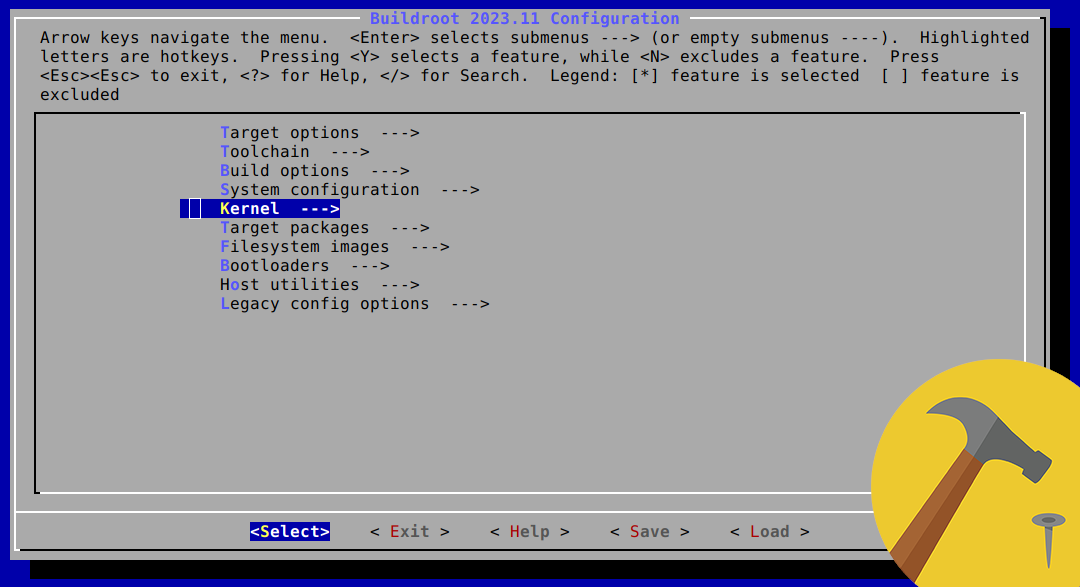
Build
The project comes with a short list of VSCode build tasks for the sample applications, that can be accesses via «CTRL+SHIFT+B».
Hardware
The TMC5160 driver has been tested with the following hardware:
- Nucleo-64 STM32F103RB board
- Watterott SilentStepStick TMC5160 (SPI only, UART pins not available)
- TRINAMIC TMC5160-BOB breakout board
- TRINAMIC TMC5160-EVAL
- own custom boards based on TMC5130 chip
POWER-UP SEQUENCE 1) apply motor voltage VM, 2) apply digital IO voltage VCC_IO. The driver IC is reset cycling VCC_IO
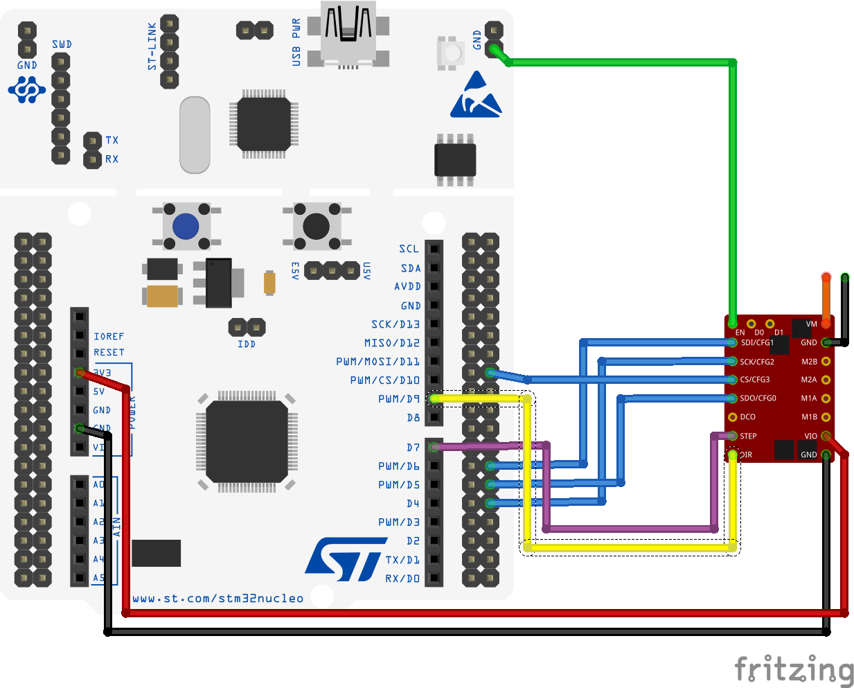
NUCLEO/TMC5160-StepStick (SPI)
HW MOD Watterott StepStick have the STEP/DIR interface enabled by default. To enable the TMC5160 internal ramp generator apply this mod TODO
UART Watterott StepStick does not support UART interface
| NUCLEO-F103RB | TMC5160 board | Description |
|---|---|---|
| GND | Ground | |
| VM | Motor Supply Voltage (10-35V) | |
| CN6 pin 4 (3V3) | VIO | Logic Supply Voltage (3.3-5V) |
| GND | EN | Enable Motor Outputs (GND=on, VIO=off) |
| CN10, PB15 (SPI2_MISO) | SDO | MISO - Serial Data Output |
| CN10, PB14 (SPI2_MOSI) | SDI | MOSI - Serial Data Input |
| CN10, PB13 (SPI2_CLK) | SCK | SCLK - Serial Clock Input |
| CN10, PB12 (SPI2_CLK) | CS | SS - Chip Select Input (no internal pu resistor) |
| CN9, PA8 (TIM1_CH1) | STEP | STEP - Step Input) |
| CN5, PC7 | DIR | DIR - Direction Input) |
| M1A/B, M2A/B | Motor Coils |
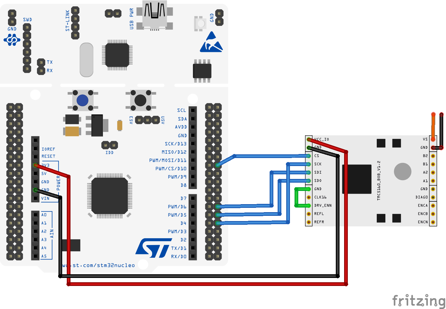
NUCLEO/TMC5160-BOB (SPI)
UART Trinamic BOB board does not support UART interface (TODO see schematic)
The table of connections is the same as for the StepStick above, while the wiring diagram is provided below.
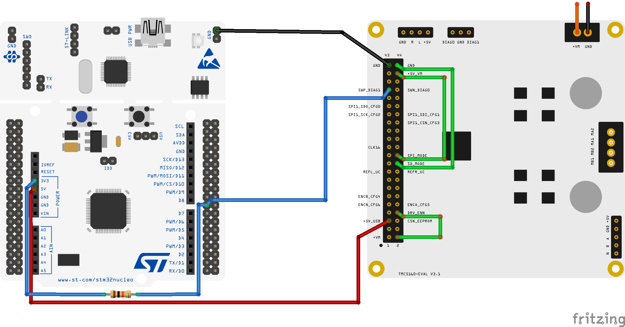
NUCLEO/TMC5160-EVAL (UART)