TL;DR
Check out the buildroot-klipper3d project on GitHub.
Overview
Klipper is a control firmware that takes a slightly different approach compared to others, splitting the workload between a SBC (typically less resource contrained), in charge of all the heavy load computation and a MCU board, tasked with the generation of the low-level signals to the actuator and from the sensors.
Klipper installation is typically done on top of OctoPi, a popular Raspbian based SD card image for the Raspberry Pi that already includes the web interface for 3D printers OctoPrint. Alternatively Klipper comes pre-packaged within a purposedly built Linux-based distribution like MainsailOS, along with the Moonraker API server and interfaces like Mainsail or Fluidd.
Buildroot, on the other hand, is a simple, efficient and easy-to-use tool to generate embedded Linux systems through cross-compilation. It is based on a kernel-like configuration interface (menuconfig and alike), relies only on the well-known Makefile language and has a simple structure that makes it easy to understand and extend.
No other Klipper package exists for Buildroot, although the topic has been discussed before on Klipper’s GitHub and Discourse.
Implementation
Normally, Klipper installation includes the following steps:
-
prepare an OS image, running a script that will download Klipper install dependencies, set Python venv and setup Klipper to run at system startup
- build the MCU firmware (kconfig)
- flash the MCU firmware
- Configuring Klipper (printer config)
- additionally, a mechanism exists within Klipper that builds Klipper host (klippy) C code at run time, every time it’s needed
Integrating Klipper into the Buildroot build system means to create a package with the proper Makefile and Kconfig file capable of performing all the steps described above (see klipper3d package)
The following sections describe the key aspects of this implementation.
Multiple cross-compile: a tale of two targets
The picture below shows the difference between the traditional Klipper installation workflow and the Buildroot workflow. Buildroot is responsible for two main task:
- cross-compile the Linux system for the Raspberry Pi (Buildroot’s target)
- cross-compile the Klipper firmware for the MCU (Klipper’s target)
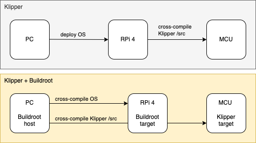
Klipper default workflow vs Buildroot workflow
Buildroot configuration
Starting from the default raspberrypi4_defconfig a number of changes have been introduced, in raspberrypi4_klipper3d_defconfig, to build and run Klipper successfully.
-
an explicit Buildroot version, pre 2024, is needed due to a problem found in later versions where it’s not possible to disable the ECHO of the Raspberry onboard serial port
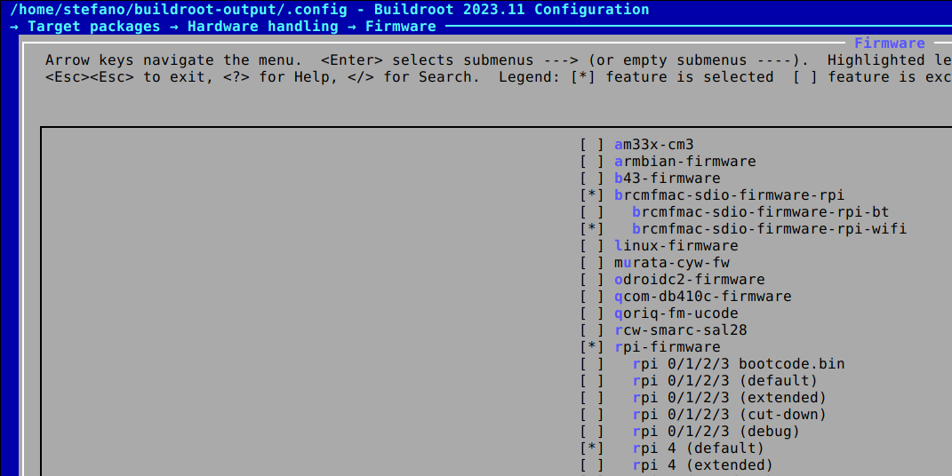
- enable the Raspberry Pi onboard UART and:
-
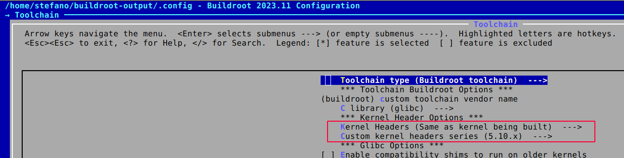
the GNU ARM Embedded Toolchain 10.3-2021.10 (pre 2022, and now deprecated) is added as a dependency to compiler Klipper firmware successfully, as building with later toolchain version will trigger an error.
-
Klipper dependencies are added to the Config.in file
- Python 3 is used to run Klipper and the klippy-requirements are once again taken care of in the Config.in file
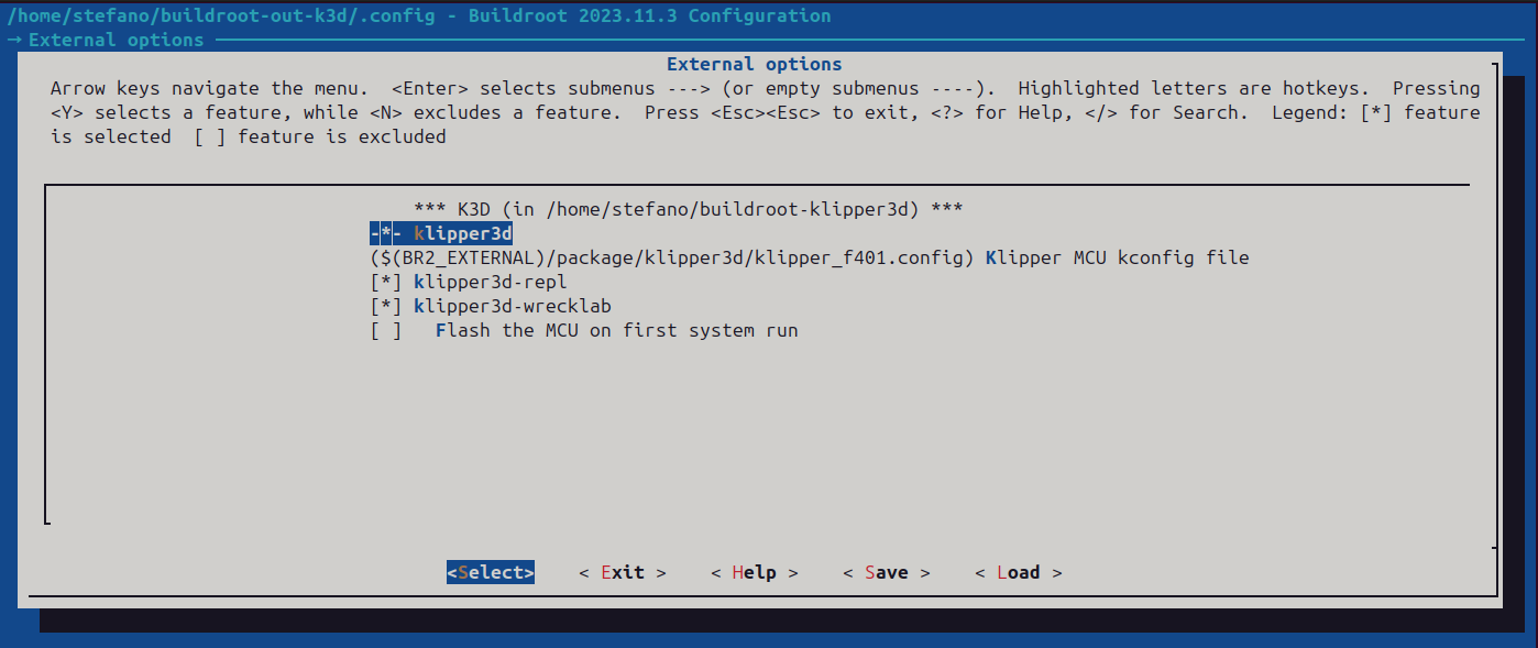
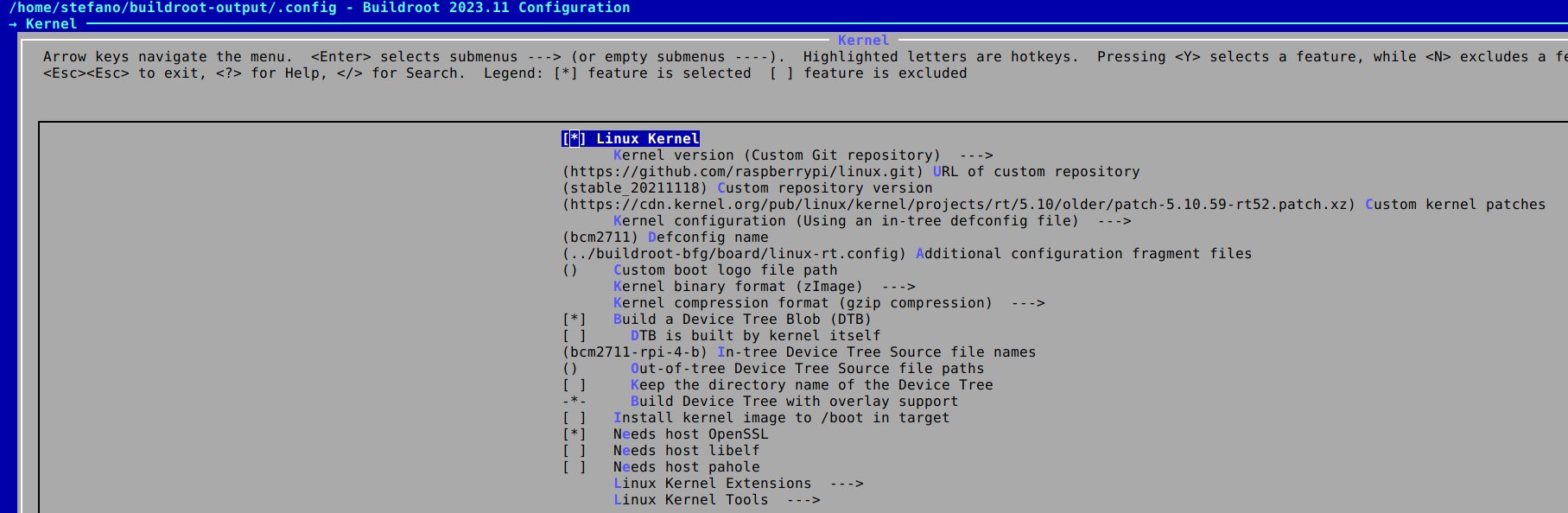
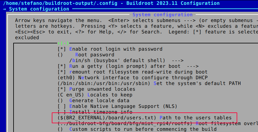
Klipper menuconfig
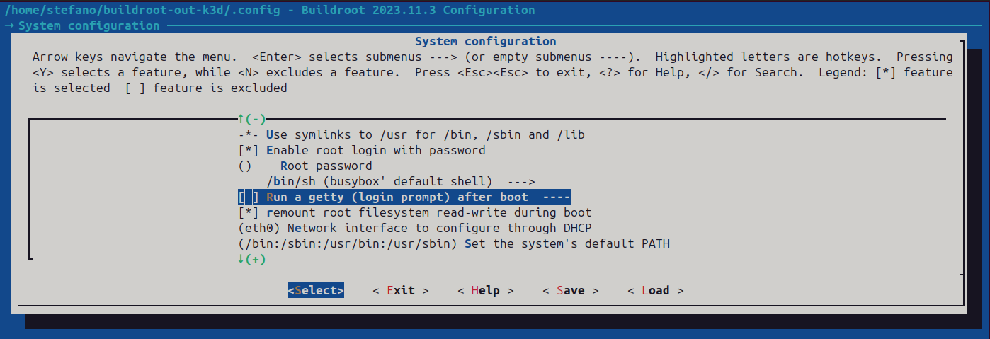
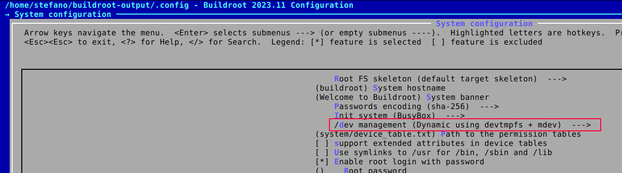
Disable getty from the serial console
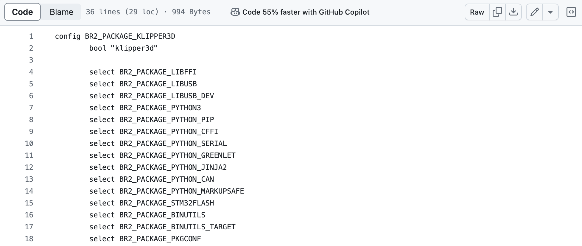
Klippy dependencies
ONBOARD UART - Point 1 and 2 are needed if your control board is connected to the Raspberry Pi via the onboard serial port on the GPIO connector. They might be unnecessary when using an USB to serial adapter.
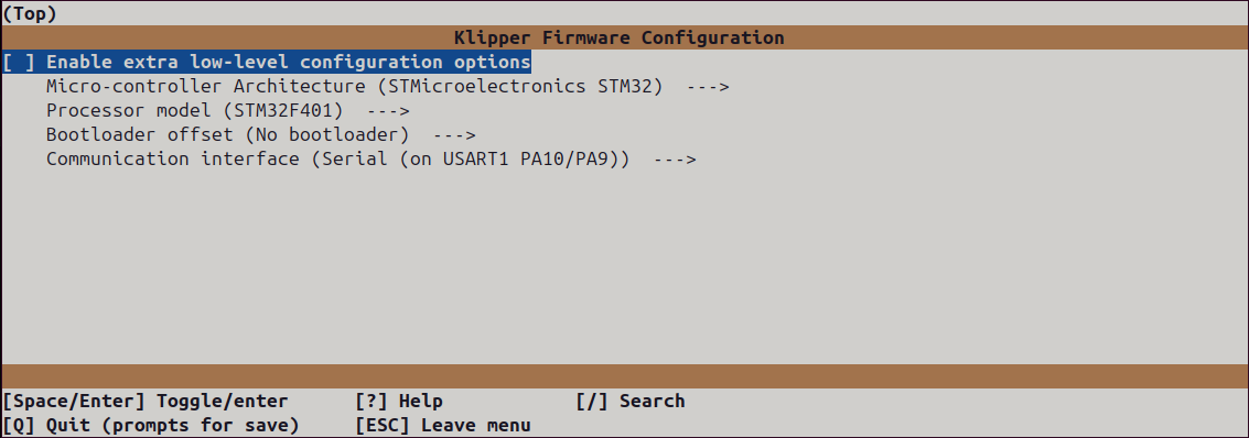
Klipper firmware configuration
Klipper MCU configuration can be reached within the Buildroot build system:
make klipper3d-menuconfig
Additional packages
klipper-repl
klipper-repl has also been ported to Buildroot to provide a minimal interface to control Klipper from the command line.
KlipperScreen
The porting of KlipperScreen is PLANNED.
klipper-wrecklab
klipper-wrecklab is a package that adds support for the printHAT control boards from Wrecklab.
Not supported
Moonraker API server is not currently supported as its installation depends on the standard ip command that can output data in json format. BusyBox, on which Buildroot is based, provides its own ip command that does not include the option for JSON output.
As a consequence Mainsail, which relies on the Moonraker server, is also not supported.