A Developers’ Guide to KiMotor
KiMotor plugin explained from a developer’s point of view
Overview
KiMotor automates the design of PCB motors. The process is controlled by a set of parameters that a user can provide via a wxPython GUI, designed with wxformbuilder. The parameters describe the features of the PCB motor that are created according to the following workflow:
Definitions
Terminology
TODO: add picture
| slot | Conventional motor’s slots are mechanical features of the stator, resembling teeth, which allow for the motor windings to be wound onto. In a KiMotor PCB, the slot is the way the “active” area of the stator is partitioned (it spans an angle of 2*pi/n_slots) |
| coil | Series of turns made up of PCB tracks, either straight lines or arcs, all contained onto a single PCB layer |
| winding | Motor windings are loops of copper wire, packed together to achieve high copper density for a given volume (around one or more motor slot). In KiMotor a winding is a multi-layer stack of coils. The current version of KiMotor only supports concentrated windings, so each winding is fully contained inside a single slot. |
| rings | A ring, or phase ring are circular areas laying between the motor windings and the motor shaft bore. They contain arc tracks and junctions that connects multiple windings to form a motor phase. |
| waypoints | Locations in the XY-plane used to define the shape of a coil |
Further references at Circuit Globe and OSWOS
Reference Frame and Units
In KiCad’s internal coordinate system X increases from left to right, which is normal, but Y increases from top to bottom. The reason is historical and KiCad users that are bothered by this behavior can change it. However, as a developer interacting programmatically with the system, you have to deal with the reference frame described above, which is the one always used in the background.
KiCad system resolution is 1nm. When expressed in this way, coordinates can be treated as integers (e.g. VECTOR2I type).
KiMotor dimensions are given in mm and stored as floating point. They’re converted internally via pcbnew.IU_PER_MM (< KiCad 7) or pcbnew.FromMM(1) (KiCad 7) scaling factor.
KiMotor might internally convert 2D to 3D coordinates (think of them as VECTOR3I, with Z=0) to simplify some of the vector calculations used for coil planning and fillets.
KiMotor refers to a coil being clockwise (CW) or counter-clockwise (CCW) turning, from the point of view of an observer that looks down from the Z+ axis, and runs the waypoints from the first to the last (ascending indexes).
Note that, as the reference frame used is a right-hand one, the CW / CCW rotation are inverted for an user looking at the screen (as he looks up from the Z- axis)
Naming convention
The source code tries to stick to the following prefix/suffix as much as possible:
| r_ | radial locations (in polar coordinates) |
| th_ | angles, in radians (in polar coordinates) |
| xy_ | points in the 2D space (in cartesian coordinates) |
| wp_ | coil waypoints in 3D space (in cartesian coordinates) |
| n_ | length of array-like objects |
| _s | start/first point (of a line, arc, track, coil, etc.) |
| _e | end/last point (of a line, arc, track, coil, etc.) |
| _cw | waypoints ordered for a clockwise turning coil |
| _ccw | waypoints ordered for a counter-clockwise turning coil |
Generating the motor windings
At the core of the KiMotor functionalities lies the ability to parametrically generate the motor windings, across multiple PCB layers:
-
a coil_planner is called to generate the waypoints that describe a particular shape of coil, rotating CW
-
a coil_tracker is called to connect the waypoints into straight or arc PCB tracks that form the single-layer coil
-
the waypoints are transformed (mirrored around X) to make a template for the next layer, rotating CCW, then they’re tracked
-
the CW/CCW alternating coils are created for all the PCB layers needed, then they’re connected to make a winding
Coil Planner
A coil planner is responsible for “solving a coil”, which is, to calculate a series of waypoints properly spaced on the XY-plane such as to describe a certain coil geometry, within the given constraints (e.g., inner and outer radius, coil “width”, shape).
The waypoints generated by the planner are used as a template. They’re capable of representing the coils on any layer at any angular position, when proper rotation matrixes are applied (to rotate around X and Z axis).
The waypoints generated are ordered from the outermost end of the coil to the innermost. However, there’s no explicit information returned about a waypoint role (e.g. if it is a line endpoint or an arc mid point) that is left to the coil tracker to define.
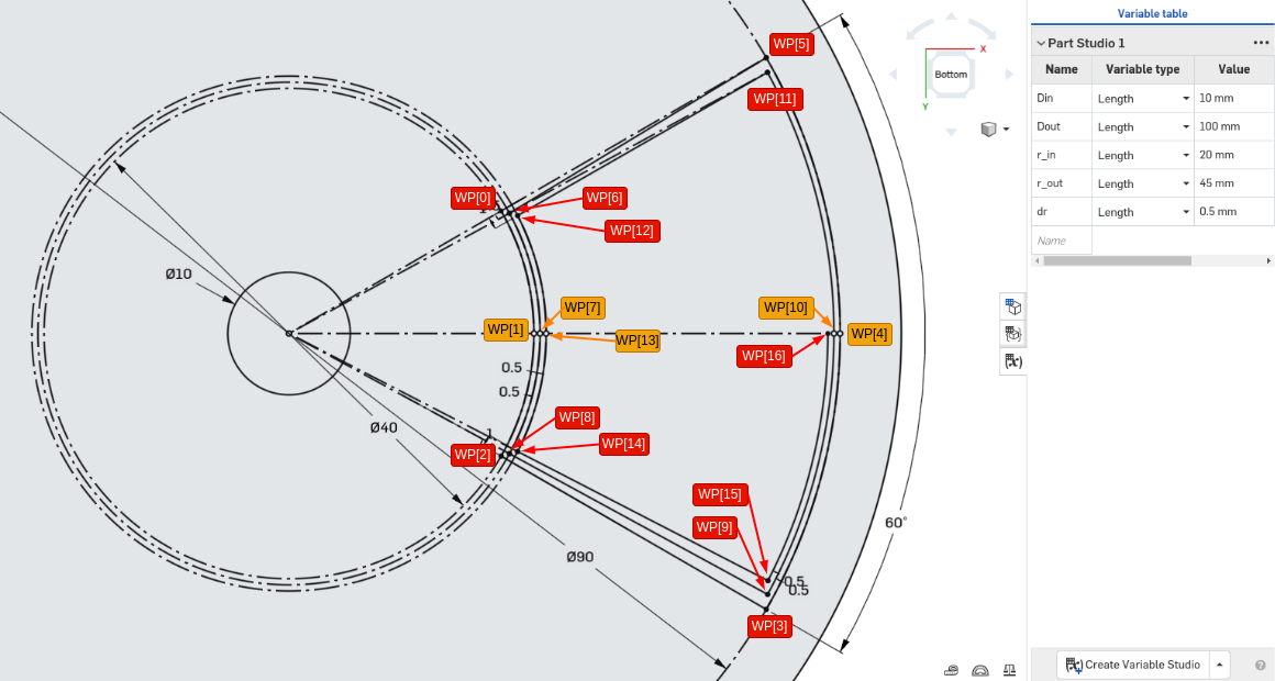 Fig.1 - Ordered waypoints from the planner, for a CW-turning coil
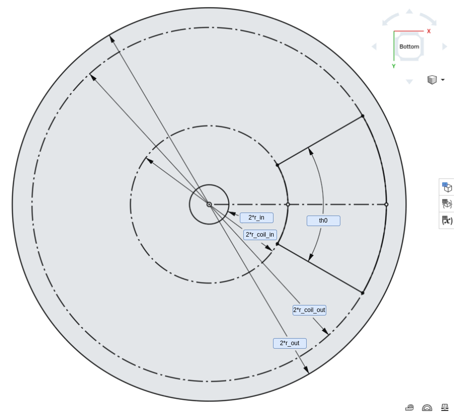 Fig.2 - Anatomy of a PCB motor
Coil Tracker
TODO: add description
From Coil to Winding
TODO: add description
Fillet: make that coil prettier
Making the coil look nice requires adding some fillet at every sharp corner. That said, actually doing it turns out to be quite a feat.
The geometry and linear algebra involved can be found in kimotor_linalg.py.
It works. It can be improved, though.
Wiring the motor
The remaining of the motor wirings can be divided into two groups, the phase rings and junctions and the motor terminals.
Phase rings
TODO: add description

Motor terminals
Motor terminals are fan out added to the first winding of each motor phase. From the starting point of the winding (inner side), a track is added that runs in between two adjacent slots up to a radial location r_term where a terminal pad is placed.